Deep Dive: T6C10
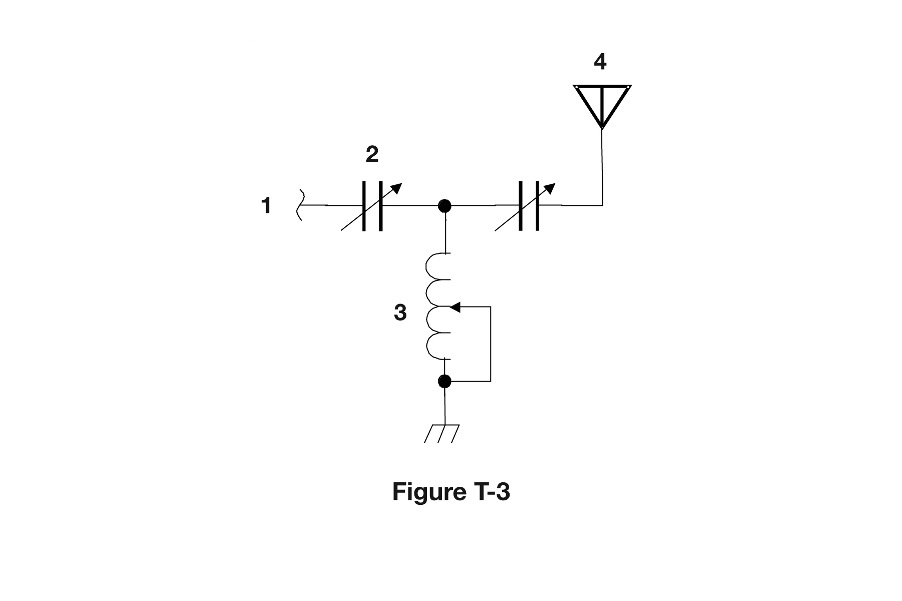
The correct answer is Variable inductor. Based on the schematic diagram in figure T-3, component 3 is a variable inductor, identified by its standard schematic symbol showing a coil (inductor symbol) with an arrow through it, indicating the inductance can be adjusted. Variable inductors allow you to change inductance values by adjusting a core position or coil configuration. For amateur radio operators, variable inductors are used in antenna tuners, RF filters, and impedance matching networks where adjustable inductance is needed for tuning. Being able to identify variable inductors in schematics helps understand tuning circuits and adjustable RF components.
Why Other Answers Are Wrong
Option A (Connector): Incorrect. Connectors are shown with multiple pins or connection points. Component 3 shows the variable inductor symbol (coil with arrow). Option B (Meter): Incorrect. Meters are shown as circles with letters (V, A, etc.) inside. Component 3 shows the variable inductor symbol. Option C (Variable capacitor): Incorrect. Variable capacitors are shown as two parallel lines (capacitor symbol) with an arrow. Component 3 shows a coil (inductor) with an arrow, not parallel lines.
Exam Tip
Variable inductor = coil symbol with arrow. The coil indicates inductance, the arrow shows it's adjustable. Variable capacitors have parallel lines with arrows. If it's a coil with an arrow, it's a variable inductor.
Memory Aid
Variable inductor = coil with arrow. Think 'V'ariable 'I'nductor = 'I'nductor (coil) with a'R'row. The coil shows inductance, arrow shows adjustability.
Real-World Example
In an antenna tuner schematic, component 3 might be a variable inductor used to adjust the matching network. By changing the inductance, you can tune the circuit to match your antenna's impedance. Understanding variable inductor symbols helps you identify tuning components in RF circuits.
Source & Coverage
Question Pool: 2026-2030 Question Pool
Subelement: T6C
Reference: 2026-2030 Question Pool · T6 - Electrical components
Key Concepts
Official Pool Source
Question text and answer key are synchronized with the current NCVEC Technician Class pool and mapped to the T6C topic.