Deep Dive: T6C09
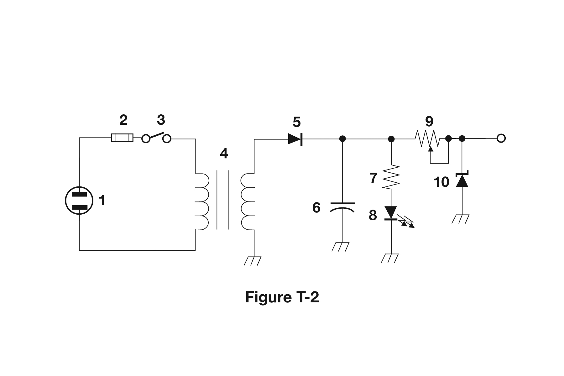
The correct answer is Transformer. Based on the schematic diagram in figure T-2, component 4 is a transformer, identified by its standard schematic symbol showing two or more coils (windings) with lines between them indicating the magnetic coupling. Transformers transfer energy between circuits through electromagnetic induction and are used for voltage transformation, impedance matching, and isolation. For amateur radio operators, transformers are found in power supplies (to step down AC voltage), audio circuits (for impedance matching), and RF circuits (for coupling and matching). Being able to identify transformers in schematics is essential for understanding power supplies and signal coupling.
Why Other Answers Are Wrong
Option A (Variable inductor): Incorrect. Variable inductors are shown as single coils with arrows. Component 4 shows multiple coils (windings) indicating a transformer. Option B (Double-pole switch): Incorrect. Switches are shown with specific switch symbols. Component 4 shows the transformer symbol with multiple windings. Option C (Potentiometer): Incorrect. Potentiometers are shown as resistor symbols with arrows. Component 4 shows the transformer symbol with coils.
Exam Tip
Transformers are shown as two or more coils (windings) with lines between them showing magnetic coupling. If you see multiple coils connected magnetically, it's a transformer. Different from single inductors (one coil) or switches (different symbols).
Memory Aid
Transformer = multiple coils (windings). Think 'T'ransformer = 'T'wo or more 'T'urns (coils) magnetically coupled. Multiple windings indicate a transformer.
Real-World Example
In a power supply schematic, component 4 might be the main transformer that steps down 120V AC to lower voltages for the circuit. This transformer has a primary winding (connected to AC input) and secondary windings (providing different voltage outputs). Understanding transformer symbols helps you trace power flow and voltage levels.
Source & Coverage
Question Pool: 2026-2030 Question Pool
Subelement: T6C
Reference: 2026-2030 Question Pool · T6 - Electrical components
Key Concepts
Official Pool Source
Question text and answer key are synchronized with the current NCVEC Technician Class pool and mapped to the T6C topic.