Deep Dive: T6C04
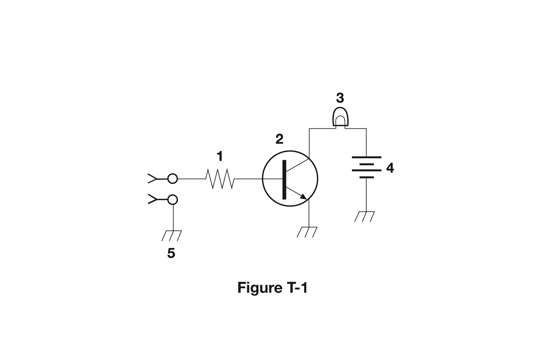
The correct answer is Lamp. Based on the schematic diagram in figure T-1, component 3 is a lamp (indicator light), identified by its standard schematic symbol which typically shows a circle with an X inside or a circle with a wavy line, representing a light bulb or LED indicator. Lamps are used as visual indicators to show circuit status, power on/off, signal presence, or other operational states. For amateur radio operators, being able to identify lamps in schematics helps understand equipment status indicators, troubleshooting non-functioning displays, and understanding circuit operation. Indicator lamps are commonly found in transceivers, power supplies, and test equipment to provide visual feedback about system status.
Why Other Answers Are Wrong
Option A (Resistor): Incorrect. Resistors are shown as zigzag lines or rectangles with two terminals. Component 3 shows the lamp/indicator symbol, not a resistor. Option B (Transistor): Incorrect. Transistors have three terminals in a specific configuration. Component 3 shows the lamp symbol, which is distinctly different. Option D (Ground symbol): Incorrect. Ground symbols are typically shown as horizontal lines with vertical lines beneath, or as a triangle. Component 3 shows the lamp/indicator symbol.
Exam Tip
Lamps/indicators are shown as circles with X or wavy lines inside. If you see this symbol in a schematic, it's a lamp or indicator light. Resistors are zigzag lines, transistors have three terminals, and ground has a different symbol.
Memory Aid
Lamp = circle with X or wavy line. Think 'L'amp = 'L'ight symbol (circle with lines inside). Different from resistor (zigzag) or transistor (three terminals).
Real-World Example
In your transceiver's schematic, component 3 might be the power indicator lamp. When you turn on the radio, this lamp lights up to show the unit is powered. Being able to identify this in the schematic helps you understand the power indication circuit and troubleshoot if the indicator doesn't work.
Source & Coverage
Question Pool: 2026-2030 Question Pool
Subelement: T6C
Reference: 2026-2030 Question Pool · T6 - Electrical components
Key Concepts
Official Pool Source
Question text and answer key are synchronized with the current NCVEC Technician Class pool and mapped to the T6C topic.