Deep Dive: T6C03
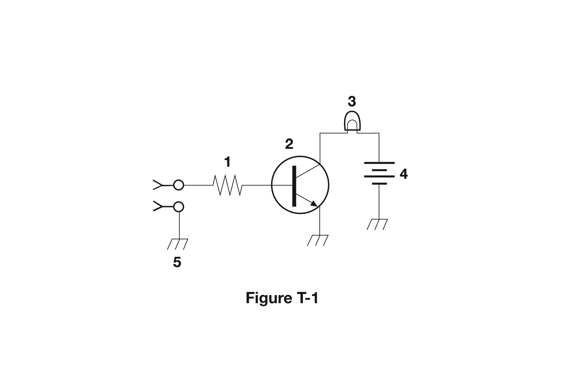
The correct answer is Transistor. Based on the schematic diagram in figure T-1, component 2 is a transistor, identified by its standard schematic symbol showing three terminals (typically emitter, base, and collector for a bipolar junction transistor). Transistors are active semiconductor devices used for amplification, switching, and signal processing. In schematics, transistors have distinctive symbols that clearly show the three terminals and the type of transistor (NPN, PNP, FET, etc.). For amateur radio operators, being able to identify transistors in schematics is essential for understanding amplifier circuits, switching functions, and signal processing stages. Transistors are key components in virtually all modern radio equipment.
Why Other Answers Are Wrong
Option A (Resistor): Incorrect. Resistors are shown as zigzag lines or rectangles with two terminals. Component 2 shows three terminals in a transistor configuration, not a resistor. Option C (Indicator lamp): Incorrect. Indicator lamps (LEDs or bulbs) have different symbols, often showing a circle with an X or specific light-emitting symbols. Component 2 shows the transistor symbol with three terminals. Option D (Connector): Incorrect. Connectors show multiple connection points but in a different configuration than transistors. Component 2 clearly shows the three-terminal structure of a transistor.
Exam Tip
Transistors have three terminals in schematics - emitter, base, collector for BJTs or gate, drain, source for FETs. If you see a component with three terminals in a transistor configuration, it's a transistor. Resistors have two terminals, and lamps/connectors have different symbols.
Memory Aid
Transistor = three terminals. Think 'T'ransistor has 'T'hree terminals (emitter, base, collector). Different from two-terminal components like resistors.
Real-World Example
In the schematic for an RF amplifier, component 2 is shown as a transistor with its base connected to the input signal, emitter to ground, and collector to the output through a load resistor. This transistor amplifies the weak RF signal. Being able to identify this as a transistor helps you understand that this is an active amplification stage, not just passive components like resistors or capacitors.
Source & Coverage
Question Pool: 2026-2030 Question Pool
Subelement: T6C
Reference: 2026-2030 Question Pool · T6 - Electrical components
Key Concepts
Official Pool Source
Question text and answer key are synchronized with the current NCVEC Technician Class pool and mapped to the T6C topic.