Deep Dive: E9B01
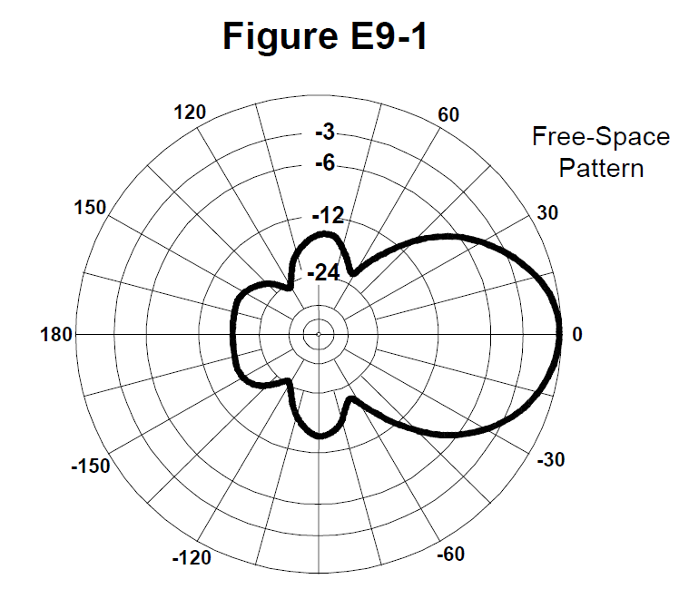
The correct answer is B: 50 degrees. The 3 dB beamwidth of the antenna radiation pattern shown in Figure E9-1 is 50 degrees. The 3 dB beamwidth is the angular width where the power drops to half (3 dB down) from the peak. The 3 dB beamwidth is measured on the radiation pattern by finding the points where the signal strength is 3 dB below the peak. The angular separation between these two points is the 3 dB beamwidth. This is an important parameter because it tells you how directional the antenna is - narrower beamwidth means more directional. The 3 dB beamwidth is a standard way to specify antenna directivity and is commonly used in antenna specifications.
Why Other Answers Are Wrong
Option A: Incorrect. 75 degrees would be too wide for the pattern shown. The 3 dB beamwidth is narrower than this. Option C: Incorrect. 25 degrees would be too narrow. The pattern shows a wider beamwidth. Option D: Incorrect. 30 degrees is also too narrow. The correct value from the figure is 50 degrees.
Exam Tip
3 dB beamwidth = Read from pattern. Remember: The 3 dB beamwidth is the angular width where power is 3 dB below peak. For Figure E9-1, it's 50 degrees.
Memory Aid
**3** dB **B**eamwidth = **5**0 degrees (think '3BB = 50°')
Real-World Example
You're analyzing an antenna radiation pattern. The pattern shows the signal is strongest at 0 degrees. You find the points where the signal drops to half power (3 dB down) - these occur at -25 degrees and +25 degrees. The 3 dB beamwidth is 50 degrees (the total angular width between the 3 dB points).
Source & Coverage
Question Pool: 2024-2028 Question Pool
Subelement: E9B
Reference: FCC Part 97.3
Key Concepts
Official Pool Source
Question text and answer key are synchronized with the current NCVEC Extra Class pool and mapped to the E9B topic.