Deep Dive: E7D08
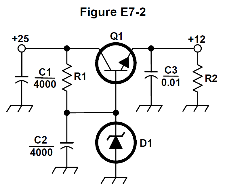
The correct answer is C: Linear voltage regulator. What type of circuit is shown in Figure E7-2 is a linear voltage regulator. Figure E7-2 shows a linear regulator circuit. For amateur radio operators, this is important for power supply design. Understanding this helps when analyzing regulator circuits.
Why Other Answers Are Wrong
Option A (Switching voltage regulator): Incorrect. Switching regulator isn't the type - Figure E7-2 shows linear regulator. Switching regulator isn't the type. Option B (Common emitter amplifier): Incorrect. Common emitter amplifier isn't the type - Figure E7-2 shows linear regulator. Common emitter isn't the type. Option D (Common base amplifier): Incorrect. Common base amplifier isn't the type - Figure E7-2 shows linear regulator. Common base isn't the type.
Exam Tip
Circuit type in Figure E7-2 = linear voltage regulator. Think 'L'inear 'R'egulator = 'L'inear 'R'esistance (pass transistor). Figure E7-2 shows a linear regulator circuit. Not switching regulator, not common emitter, not common base - just linear voltage regulator.
Memory Aid
Circuit type in Figure E7-2 = linear voltage regulator. Think 'L'inear 'R'egulator = 'P'ass transistor. Figure E7-2 shows a linear regulator circuit. Important for power supply design.
Real-World Example
The circuit shown in Figure E7-2: It's a linear voltage regulator. The circuit uses a pass transistor (Q1) to regulate voltage linearly. This is the type - linear voltage regulator.
Source & Coverage
Question Pool: 2024-2028 Question Pool
Subelement: E7D
Reference: 2024-2028 Question Pool · E7 - Practical Circuits
Key Concepts
Official Pool Source
Question text and answer key are synchronized with the current NCVEC Extra Class pool and mapped to the E7D topic.