Deep Dive: E6A11
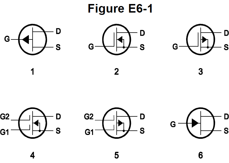
The correct answer is A: 1. In Figure E6-1, which is the schematic symbol for a P-channel junction FET is 1. Symbol 1 represents a P-channel junction FET. For amateur radio operators, this is important for transistor knowledge. Understanding this helps when reading schematics.
Why Other Answers Are Wrong
Option B (2): Incorrect. Symbol 2 isn't P-channel junction FET - symbol 1 is. Symbol 2 is wrong. Option C (3): Incorrect. Symbol 3 isn't P-channel junction FET - symbol 1 is. Symbol 3 is wrong. Option D (6): Incorrect. Symbol 6 isn't P-channel junction FET - symbol 1 is. Symbol 6 is wrong.
Exam Tip
P-channel junction FET symbol in Figure E6-1 = 1. Think 'P'-channel 'J'unction 'F'ET = '1'. Symbol 1 represents a P-channel junction FET. Not 2, not 3, not 6 - just 1.
Memory Aid
P-channel junction FET symbol in Figure E6-1 = 1. Think 'P'-channel 'J'unction 'F'ET = '1'. Symbol 1 represents a P-channel junction FET. Important for transistor knowledge.
Real-World Example
In Figure E6-1: Symbol 1 is the schematic symbol for a P-channel junction FET. This symbol shows a P-channel JFET. This is the symbol - 1 for P-channel junction FET.
Source & Coverage
Question Pool: 2024-2028 Question Pool
Subelement: E6A
Reference: 2024-2028 Question Pool · E6 - Circuit Components
Key Concepts
Official Pool Source
Question text and answer key are synchronized with the current NCVEC Extra Class pool and mapped to the E6A topic.