Deep Dive: G7A13
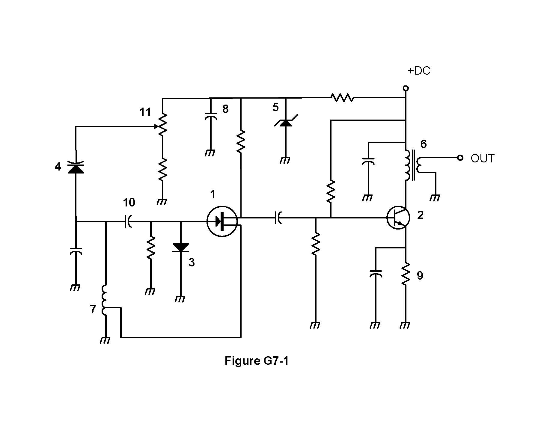
The correct answer is A: Symbol 7. The symbol in figure G7-1 that represents a tapped inductor is Symbol 7. Tapped inductor symbols show an inductor with a tap (connection point) along the winding. For amateur radio operators, this is important for reading circuit diagrams. Understanding this helps when working with tapped inductor circuits.
Why Other Answers Are Wrong
Option B (Symbol 11): Incorrect. Symbol 11 represents a different component - likely another device, not a tapped inductor. Tapped inductors have distinct symbols. Option C (Symbol 6): Incorrect. Symbol 6 represents a solid core transformer, not a tapped inductor. Transformers and tapped inductors have different symbols. Option D (Symbol 1): Incorrect. Symbol 1 represents a FET, not a tapped inductor. FETs and tapped inductors have different symbols.
Exam Tip
Tapped inductor symbol = Symbol 7. Think 'T'apped 'I'nductor = 'S'ymbol '7'. Tapped inductor symbols show inductor with tap (connection point) along winding. Not Symbol 1 (FET), not Symbol 6 (transformer), not Symbol 11 - just Symbol 7.
Memory Aid
Tapped inductor symbol = Symbol 7. Think 'T'apped 'I'nductor = 'S'ymbol '7'. Tapped inductor symbols show inductor with tap along winding. Standard tapped inductor symbol representation.
Real-World Example
You read a circuit diagram. Symbol 7 shows a tapped inductor with a connection point (tap) along the winding. This allows access to different inductance values from the same inductor. This is how tapped inductors are represented in circuit diagrams.
Source & Coverage
Question Pool: 2023-2027 Question Pool
Subelement: G7A
Reference: 2023-2027 Question Pool · G7 - Practical Circuits
Key Concepts
Official Pool Source
Question text and answer key are synchronized with the current NCVEC General Class pool and mapped to the G7A topic.