Deep Dive: E5C11
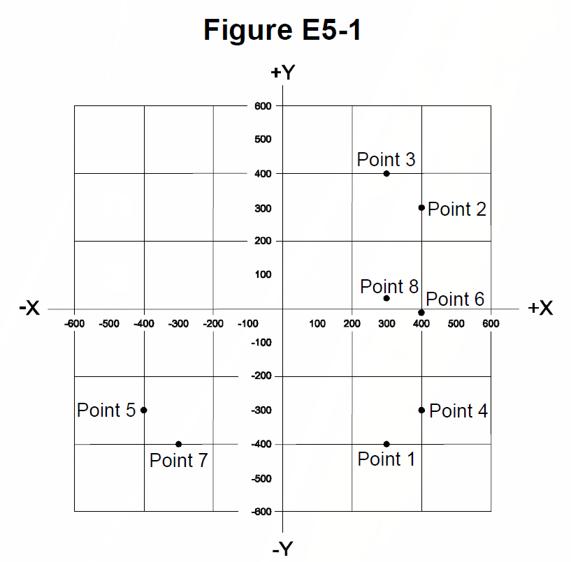
The correct answer is B: Point 3. Which point in Figure E5-1 best represents the impedance of a series circuit consisting of a 300-ohm resistor and an 18-microhenry inductor at 3.505 MHz is Point 3. At 3.505 MHz, XL = 2πfL ≈ 400Ω. Impedance ≈ 300 + j400, which corresponds to Point 3. For amateur radio operators, this is important for circuit analysis. Understanding this helps when reading impedance charts.
Why Other Answers Are Wrong
Option A (Point 1): Incorrect. Point 1 doesn't represent this impedance - Point 3 does. Point 1 is wrong. Option C (Point 7): Incorrect. Point 7 doesn't represent this impedance - Point 3 does. Point 7 is wrong. Option D (Point 8): Incorrect. Point 8 doesn't represent this impedance - Point 3 does. Point 8 is wrong.
Exam Tip
300Ω resistor + 18μH inductor at 3.505 MHz = Point 3 on Figure E5-1. Think '3'00Ω + '1'8μH at '3'.505 MHz = 'P'oint '3'. At 3.505 MHz, XL ≈ 400Ω, impedance ≈ 300 + j400, Point 3. Not Point 1, not Point 7, not Point 8 - just Point 3.
Memory Aid
300Ω resistor + 18μH inductor at 3.505 MHz = Point 3 on Figure E5-1. Think '3'00Ω + '1'8μH = 'P'oint '3'. At 3.505 MHz, XL ≈ 400Ω, impedance ≈ 300 + j400, Point 3. Important for circuit analysis.
Real-World Example
A series circuit with 300-ohm resistor and 18-microhenry inductor at 3.505 MHz: At 3.505 MHz, XL = 2π×3.505×10^6×18×10^-6 ≈ 400Ω. Impedance ≈ 300 + j400 ohms. On Figure E5-1, this corresponds to Point 3. This is the point - Point 3.
Source & Coverage
Question Pool: 2024-2028 Question Pool
Subelement: E5C
Reference: 2024-2028 Question Pool · E5 - Electrical Principles
Key Concepts
Official Pool Source
Question text and answer key are synchronized with the current NCVEC Extra Class pool and mapped to the E5C topic.